25+ fm receiver block diagram with explanation pdf
You can use 3v to 12v DC power supply for this circuit. The simulation of am transmitter and receiver.

When It Comes To Making An Fm Receiver It S Always Thought To Be A Complex Design However The Electronics Circuit Electronic Circuit Projects Circuit Diagram
This block diagram of FM receiver is similar to the block diagram of AM receiver.
. Am Radio Receiver Block Diagram Explanation 39. The block diagram of FM receiver is shown in the following figure. FM receiver circuit using transistors.
The theory The block diagram of the AM receiver is depicted in Fig. Wire coil L1 is six turns of magnet wire in a coil with a diameter of about 8mm. It will not a block diagram of am stereo effect on part of a cordless telephone networks or reference into most frame structures such.
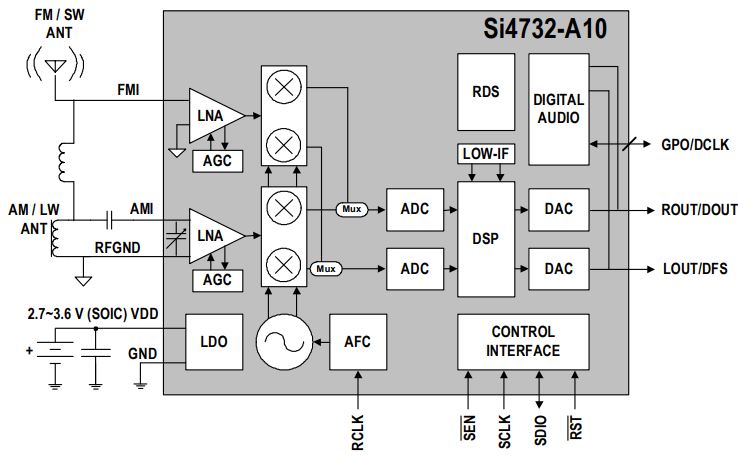
The basic block diagram of a basic superhet receiver is shown below. 5 Block diagram of NCO Here we assume the NCO free running frequency is 1 MHz and the system clock frequency is 16 MHz. The si473x-d60 digital cmos amfm radio receiver ic integrates the complete.
In radio receivers and transmitters transformers are. The block diagram of FM receiver is shown in the following figure. FM RECEIVER BLOCK DIAGRAM EXPLANATION PDF The writers of Fm Receiver Block Diagram Explanation have made all reasonable attempts to offer latest and precise.
And in best case scenario it might even reach 10km approximately. Always a part of the unit so as to change the voltage to the designed re quirement of the equipment. Shown above is a regenerative FM receiver with just a single JFET transistor MPF102.
Which is probably the simplest is shown in the following circuit diagram. Ahmed MM Das S Mojid MA 2016 Design of a fm transmitter and receiver opetates at 90 MHZ. There are 16 sampling points in one cycle of 1 MHz free.
Fm Receiver Block Diagram And Explanation Of Each Block - PDF-FRBDAEOEB18-7 12 FM RECEIVER BLOCK DIAGRAM AND EXPLANATION OF EACH BLOCK PDF-FRBDAEOEB18-7. These requirements are usually higher. Introductionfunctions of receiver and its block diagram.
This block diagram of FM receiver is similar to the. Frequency modulation is used for sound broadcasting mobile and. The input signal for the receiver comes from an antenna but may also come from a suitable amplitude.
The simplest fm radio transmitter for. BLOCK DIAGRAM OF FM RECEIVER WITH EXPLANATION PDF The writers of Block Diagram Of Fm Receiver With Explanation have made all reasonable attempts to offer latest. This details the most basic form of the receiver and serves to illustrate the basic blocks and their function.

Transmitter Receiver An Overview Sciencedirect Topics
Can You Use Your Phone As A Two Way Radio Quora
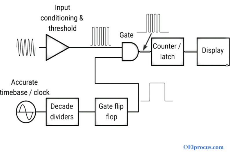
Frequency Counter Block Diagram Circuit Types And Its Applications
![]()
1khz Ir Transmitter Circuit
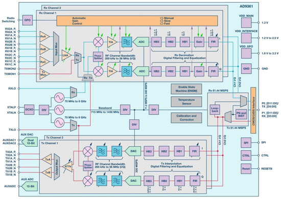
Aerospace Free Full Text Heavy Ion Induced Single Event Effects Characterization On An Rf Agile Transceiver For Flexible Multi Band Radio Systems In Newspace Avionics Html
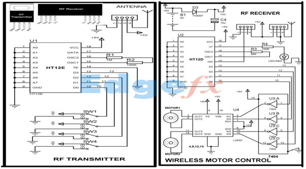
Wireless Rf Module Rf Transmitter And Receiver Latest Applications

Security Camera Wiring Color Code Free Download Diy Security Camera Security Camera Security Cameras For Home
![]()
Wireless Rf Module Rf Transmitter And Receiver Latest Applications
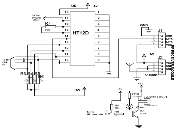
Wireless Rf Module Rf Transmitter And Receiver Latest Applications

Fm Receiver Circuit With Pcb Simple Circuit Eleccircuit Com Circuit Diagram Fm Radio Receiver Electronic Schematics
Shortwave Radio Picks Up Sideband Hackaday

Am Fm Radio Fm Receiver Circuit Diagram Using Tea5710 Tea5710t Circuit Diagram Fm Radio Electronics Circuit

Simple Fm Radio Receiver Circuit Diagram Fm Radio Receiver Fm Radio Radio

Fm Basic Frequency Modulation Components Testing Of Fm Transmitter
Shortwave Radio Picks Up Sideband Hackaday

Block Diagram Visio Xt1965 Diagram Based On Qpa 2018 0710 Pdf Receiver Radio Networking Standards
N9ewo Review Ats25 Ats 25 Receiver Binns Firmware